Dynamic Admittance Parameterization of Non-Prehensile Multi-Robot Transport with Optimal Coordinated Planning

Calvin Stahoviak1, Xavier Barr1, G. Matthew Fricke1, Sachi Barnaby1, Melanie E. Moses1,2,3, Jonathon E. Slightam4
1Department of Computer Science, University of New Mexico, 2Department of Biology, University of New Mexico, 3Santa Fe Institute, 4Sandia National Laboratories
Modeling, Estimation and Control Conference (MECC) 2026

Two mobile manipulators carry a payload with no grasp points along an S-curve. Dynamo succeeded in all 20 hardware trials; four are shown here in real time.

Abstract

Non-prehensile coordinated mobile manipulation is challenging because interactions between the robot bases and payload must be managed carefully. We present the Dynamic Admittance parameterization of Non-Prehensile Multi-robot Transport with Optimal Coordinated Planning (DYNAMO) architecture for payload transport using dual nonholonomic 4DOF mobile manipulators. DYNAMO minimizes snap and angular momentum change along a payload path and adapts arm motion to interaction forces. In hardware experiments DYNAMO achieves longer and more reliable payload transport than position-based methods, providing a practical foundation for multi-robot cooperative grasp-free manipulation.

Why Adapt the Compliance?

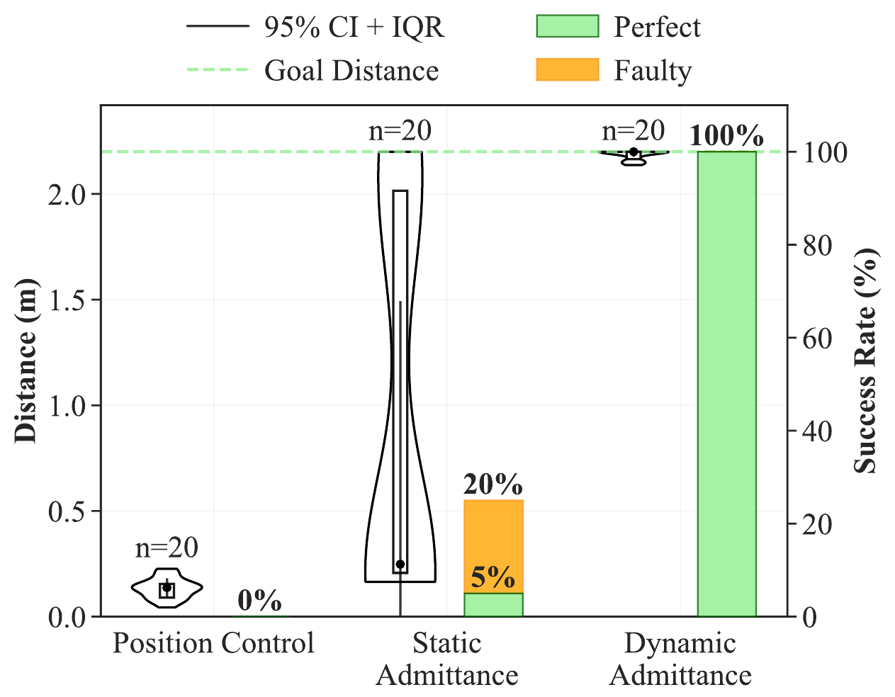
All three controllers share the same planner and base tracking, so the only difference is how the arms respond to the payload. A position controller holds the end-effectors at a fixed point inside the payload, and a static admittance controller makes each arm a mass-spring-damper with fixed parameters. Neither can absorb the drift in the distance between the robots, and the payload falls.

Position control

0% success; mean distance before the drop 0.13 m.

Static admittance control

5% perfect (25% counting faulty runs); mean distance 0.96 m.

Method

The JiANT robots
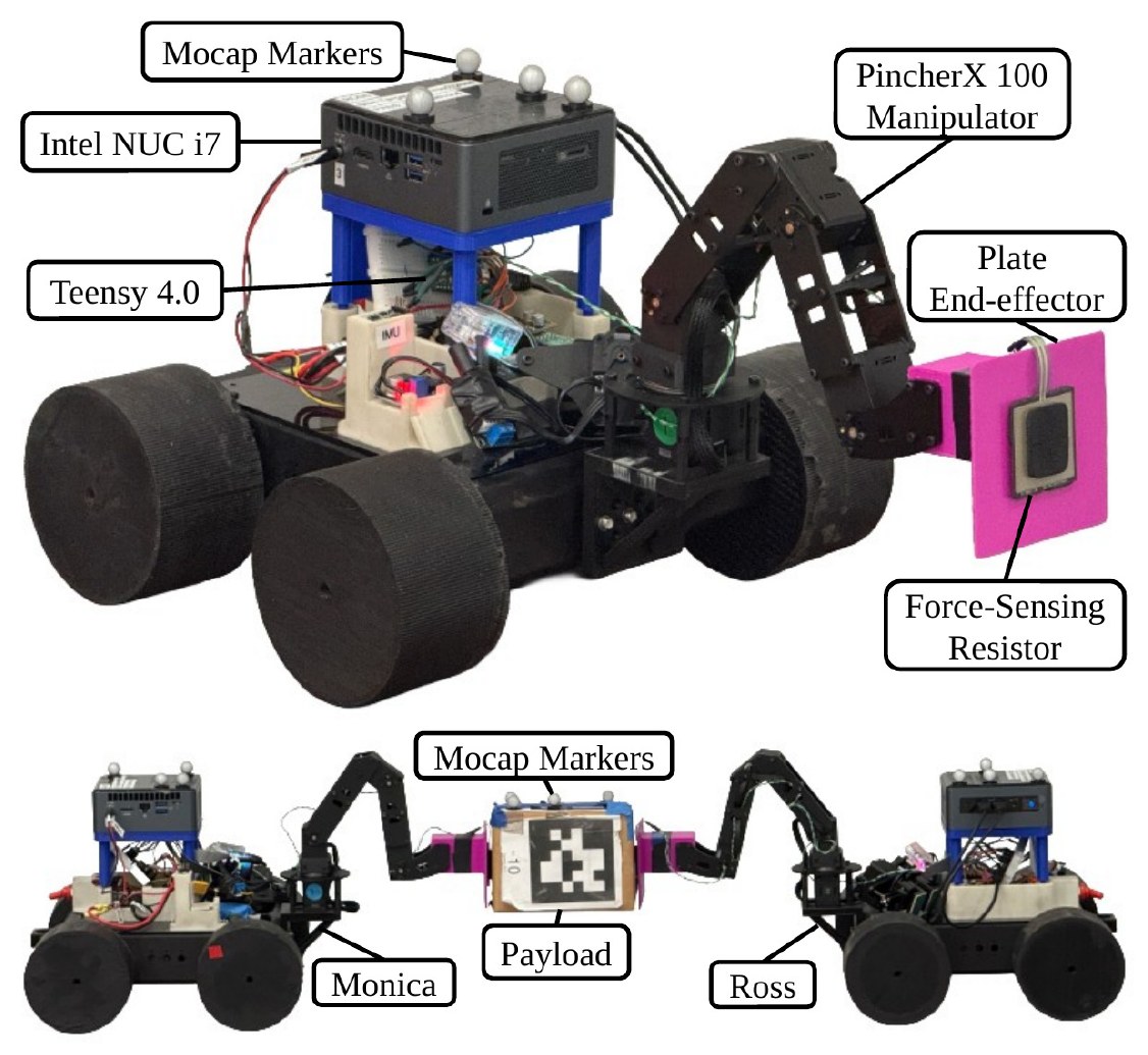
A JiANT robot with labeled components, and two JiANTs,
                  Monica and Ross, holding a payload between flat-plate
                  end-effectors.

A labeled JiANT robot (left) and the pair, Monica and Ross, holding a payload between flat-plate end-effectors (right).

Monica and Ross are Joint Integrated Admittance, Navigation, and Transport (JiANT) robots: skid-steer bases built from low-cost and 3D-printed parts. Each carries a PincherX-100 4-DOF arm whose gripper is replaced by a flat plate with a consumer-grade force-sensing resistor (FSR).

A Teensy 4.0 running micro-ROS drives the wheels, and an Intel NUC runs the ROS 2 nodes. A Vicon motion-capture system supplies the poses of both robots and the payload. The payload is an 87 g cardboard box, more than either arm's rated payload.

Control architecture

This diagram shows the full control loop for one robot. Off-board, the coordinated planner produces a desired pose, and PD and PID controllers turn the longitudinal, lateral, and heading errors measured by Vicon into velocity commands. On the base, wheel PID loops track those commands. On the arm, a parameter estimator uses the inter-robot distance to update the admittance controller, which responds to the force measured by the FSR.
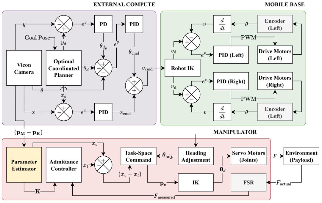
Block diagram of the control architecture, split into
              external compute, mobile base, and manipulator subsystems.

Per-robot control loop, split across off-board compute (coordinated planning and vision) and on-board compute (mobile base and manipulator control). Dynamic admittance parameterization is highlighted in yellow and computed on each robot's on-board computer in real time.

Dynamic admittance parameterization
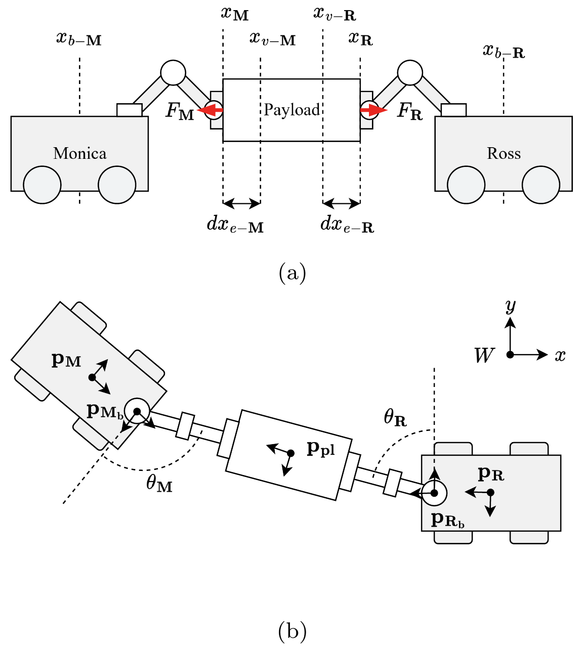
(a) Side view of the two robots and payload with virtual
                  set points and contact forces. (b) Top view with robot,
                  manipulator-base, and payload frames and heading angles.

(a) Side view of the transport setup. (b) Top view of the payload, mobile base, and manipulator base poses, with heading adjustment angles \(\theta_\mathrm{M}\) and \(\theta_\mathrm{R}\).

Each arm behaves as a mass-spring-damper about a virtual set point \(x_v\) placed inside the payload, so it presses on the box with a controlled force:

\[ F_\mathrm{ext} = M\ddot{x} + B\dot{x} + K(x - x_v) \]

With fixed parameters this only works at one inter-robot distance, and that distance changes as the bases drift. DYNAMO updates the stiffness and set point online from the error \(e = \lVert \mathbf{p}_\mathrm{M} - \mathbf{p}_\mathrm{R} \rVert\) between the robots:

Admittance parameter update rules
Virtual set point \( x_v' = x_v + \alpha_x e \)
Stiffness \( K' = K + \alpha_K e \)

Substituting these updates into the admittance law gives the full dynamic admittance parameterization:

\[ F_\mathrm{ext} = M\ddot{x} + B\dot{x} + (K + \alpha_K e)(x - x_v - \alpha_x e) \]

The gain \(\alpha_x\) keeps the virtual set point fixed relative to the payload, and \(\alpha_K\) regulates contact force as the spacing changes while keeping the damping above the critical value. The controller runs at 500 Hz, and each arm rotates so the two end-effectors stay collinear.

Optimal coordinated planning

The planner works on the payload pose \((x, y, \phi)\) and places the two bases on either side of it. A sequential convex quadratic program co-optimizes four terms: minimum snap of the payload path, minimum change of angular momentum, soft alignment of the payload yaw with the path tangent, and tracking of a reference S-path between the start and goal:

\[ \begin{aligned} \min_{X, Y, \Phi}\; & w_\mathrm{track}\left(\lVert X - X^\mathrm{ref} \rVert^2 + \lVert Y - Y^\mathrm{ref} \rVert^2\right) \\ & + w_\mathrm{snap}\left(\lVert D_4 X \rVert^2 + \lVert D_4 Y \rVert^2\right) \\ & + w_{\dot{L}} \lVert D_2 \Phi \rVert^2 + w_{\ddot{L}} \lVert D_3 \Phi \rVert^2 + w_\mathrm{align} \lVert r^{(j)} \rVert^2 \end{aligned} \]

The yaw-tangent alignment term \(r^{(j)}\) is linearized about the previous iterate, so each iteration is a banded, positive-definite QP that solves in \(O(N)\). The animation below shows the planned motion of the payload and both robots.

A render of a coordinated planned trajectory.
Results

Each controller ran 20 trials on left and right S-curves. DYNAMO completed all 20 without dropping the payload, reaching the full 2.2 m path, which was limited only by the size of the Vicon workspace. It transported the payload significantly farther than both position control and static admittance (Welch's \(t\)-test, \(p < 0.001\)).

Controller Perfect Faulty Mean distance [95% CI]
Position control 0% 0% 0.13 m [0.11, 0.16]
Static admittance 5% 20% 0.96 m [0.52, 1.4]
DYNAMO (dynamic admittance) 100% 0% 2.2 m (full path)

A faulty trial reached the goal, but the payload visibly shifted or twisted along the way.

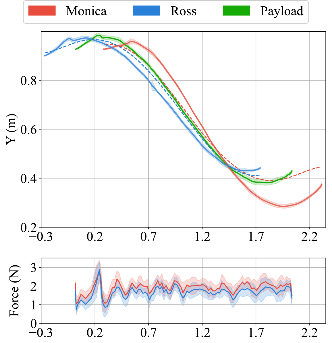
Desired and measured paths of Monica, Ross, and the
                  payload along an S-curve, with contact force below.

Trajectory and contact force under DYNAMO. Desired (dashed) and mean measured (solid) paths with standard deviation shaded. Contact forces stay bounded throughout transport.

Violin plots of distance traveled and bar chart of
                  success rate for the three controllers.

Distance traveled and success rate. Boxes show the interquartile range and black lines the 95% confidence interval of the median. Green bars are perfect trials; orange bars are faulty trials.

BibTeX

@inproceedings{stahoviak2026dynamo,
  title     = {Dynamic Admittance Parameterization of Non-Prehensile
               Multi-Robot Transport with Optimal Coordinated Planning},
  author    = {Stahoviak, Calvin and Barr, Xavier and Fricke, G. Matthew
               and Barnaby, Sachi and Moses, Melanie E.
               and Slightam, Jonathon E.},
  booktitle = {Modeling, Estimation and Control Conference (MECC)},
  year      = {2026}
}

Contact

If you have any questions, please feel free to contact Calvin Stahoviak (cjstahoviak@gmail.com).

Acknowledgments

This work was supported by Sandia subcontract 2417427, Multi-Agent Robust Intelligent Autonomous Manipulation (MARIAM), under LDRD 229360: Science of Intelligent Autonomous Manipulation (SIAM). We thank Fernando Moreu and Mahsa Sanei of the Smart Management of Infrastructure Laboratory (SMILab) for access to their Vicon system, which was supported by the Office of Naval Research, Structural Reliability ONR 331, under Grant No. 13620990 (Award No. N00014-22-1-2638) and Grant No. 13106652 (Award No. N00014-21-1-2929). We are grateful to Carter Frost for helpful discussions and early contributions to this work.

Sandia National Laboratories is a multi-mission laboratory managed and operated by National Technology & Engineering Solutions of Sandia, LLC., a wholly owned subsidiary of Honeywell International, Inc., for the U.S. Department of Energy's National Nuclear Security Administration under contract DE-NA000352. This work describes objective technical results and analysis. Any subjective views or opinions that might be expressed do not necessarily represent the views of the U.S. Department of Energy or the United States Government.